

In the realm of automotive customization and performance enhancement, installing a tachometer becomes an essential task for enthusiasts seeking precise engine monitoring. Particularly when upgrading to electronic ignition systems, understanding how to properly wire a tachometer becomes crucial.
The integration of electronic ignition systems has revolutionized the way vehicles manage spark timing and fuel delivery, enhancing efficiency and power output. Wiring a tachometer to an electronic ignition involves navigating through the intricacies of modern engine electronics, ensuring seamless communication between the tachometer and the ignition system.
This comprehensive guide aims to demystify the process, providing step-by-step instructions and insightful tips for how to wire a tachometer to electronic ignition.
From identifying the appropriate wires to establishing a secure connection, this article will empower automotive enthusiasts to successfully integrate a tachometer into their electronic ignition system, allowing them to monitor engine performance with precision and indulge in the thrilling world of customized, data-driven driving experiences.
Importance of Wiring a Tachometer Correctly to Electronic Ignition
Ensuring that a tachometer is wired correctly to an electronic ignition system is of paramount importance to guarantee accurate engine performance readouts. A tachometer that is improperly connected can produce misleading information, potentially leading drivers to make decisions that may harm their engine’s integrity or performance.
Furthermore, precise wiring is essential to avoid electrical interference that can disrupt both the vehicle’s ignition system and other sensitive electronics. By investing in the proper wiring practices, one not only safeguards the vehicle’s functionality but also extends the lifespan of the tachometer and the electronic ignition system, while enjoying an optimized performance reflective of true engine behavior.
Understanding Tachometer Wiring Basics
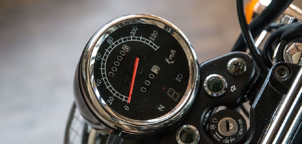
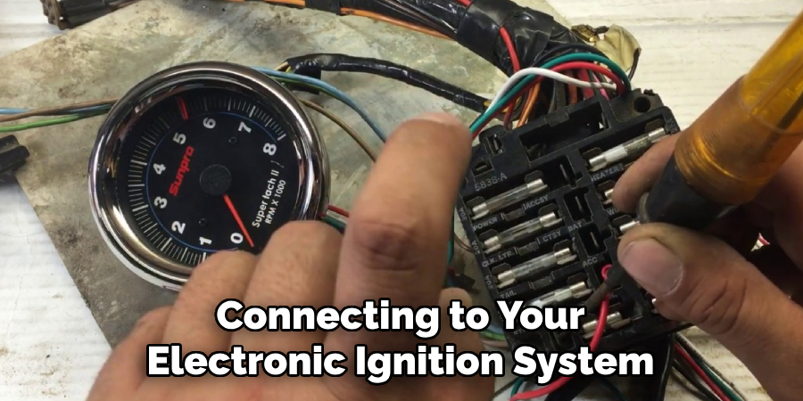
Before delving into the specifics of connecting a tachometer to your electronic ignition system, it’s critical to grasp the basics of tachometer wiring. Essentially, a tachometer reads the engine’s RPM (revolutions per minute) through electrical pulses that are generated by the ignition system.
Each pulse corresponds to a spark sent to the spark plugs, which is then translated into a RPM reading on the tachometer’s display. Wiring a tachometer accurately is all about identifying the correct wire that carries these pulses and connecting it to the signal input of the tachometer.
Moreover, the tachometer must be connected to a power source, usually through the ignition switch, and grounded properly to the vehicle’s chassis to complete its circuit. Getting these connections right is vital to the accurate operation of the tachometer and ensuring it reflects the true state of your engine’s performance.
Components of a Tachometer
When preparing to wire a tachometer, it’s beneficial to understand its key components and their roles within the system. The primary components of a tachometer include:
- The Display: This is the interface that presents the RPM readings to the user. It may be analog, with a dial and a needle, or digital, featuring numerical LED or LCD readouts.
- The Input Signal Wire: This wire receives the electrical pulses from the ignition system, which are indicative of the engine’s RPM. It’s the critical connection between the tachometer and the engine’s operation.
- The Power Wire: This connects to a switched power source within the vehicle that is only active when the ignition is turned on, ensuring that the tachometer operates only when the engine is running.
- The Ground Wire: A proper ground connection is essential for the tachometer to work correctly. This wire is usually connected to the vehicle’s chassis.
- The Lighting Wire: Some tachometers come with built-in backlighting for visibility in low-light conditions, requiring a connection to the vehicle’s lighting circuit.
Knowledge of these components is fundamental when working with tachometer installation, as it informs the proper wiring and integration into the electronic ignition system to maintain accurate and reliable functionality.
Different Types of Tachometers and Their Wiring Requirements
Tachometers come in various types and styles, each with distinct wiring requirements essential for their operation. Understanding these differences is crucial for a successful installation compatible with your electronic ignition system.
Analog Tachometers
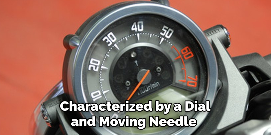
Analog tachometers are characterized by a dial and moving needle to display the RPM. They typically have a simplistic and classic look, favored in older or vintage vehicles. The wiring for analog tachometers generally involves:
- A signal input wire connected to the negative side of the ignition coil or the designated tachometer output on an electronic ignition module.
- A power wire sourced from the ignition switch to ensure the tachometer is active only when the engine is running.
- A ground wire securely attached to the vehicle’s frame.
- Some analog models may also include a wire for internal illumination.
Digital Tachometers
Digital tachometers offer a modern appearance, featuring LED or LCD displays for precise RPM readouts. Compared to analog tachometers, digital ones may require additional wiring for power and possibly a separate sensor for signal input if they do not use the standard ignition coil signal. Their wiring configuration often includes:
- A signal input wire that might connect directly to an engine management system or a dedicated sensor.
- A power wire that is connected to an accessory power source that’s only on with the ignition.
- A ground connection to the vehicle’s chassis.
- A lighting wire that ties into the instrument panel’s lighting circuit for visibility.
Standalone and Integrated Tachometers
Some tachometers are part of a larger gauge cluster, while others are standalone units. Integrated tachometers often share a common power and ground with other gauges, reducing the need for multiple connections. Standalone tachometers, conversely, will require their own dedicated wiring to the vehicle’s systems.
Contact and Non-Contact Tachometers
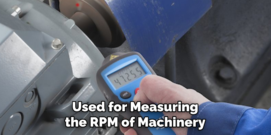
In industrial or non-automotive applications, contact and non-contact tachometers are used for measuring the RPM of machinery. Contact tachometers typically require physical attachment to the rotating component, while non-contact versions use laser or optical systems to detect rotation without direct contact. Their wiring is more specific to the machinery they are employed with.
Aftermarket High-Performance Tachometers
Performance enthusiasts might opt for high-precision aftermarket tachometers that offer features like shift lights, data logging, and customizable displays. These may have more complex wiring requirements, including additional sensors and connections to advanced engine management systems.
In each case, referring to the manufacturer’s installation instructions is imperative, as wiring specifics can vary significantly between different models and types. It’s also advised to have a detailed wiring diagram of your vehicle’s ignition system to ensure the tachometer is integrated without interference.
10 Methods How to Wire a Tachometer to Electronic Ignition
1. Identify the Tachometer Signal Wire:
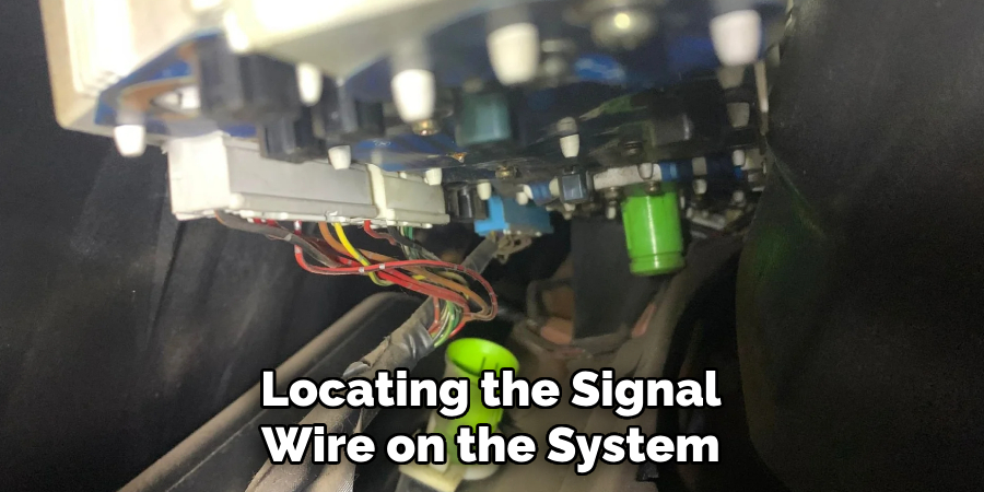
Begin by locating the signal wire on the electronic ignition system. This wire carries the RPM signal that the tachometer needs to measure engine speed. The color of the wire may vary depending on the make and model of your vehicle, but it is typically a green or white wire.
To ensure accurate readings, it’s important to connect the tachometer signal wire directly to the ignition system. This can usually be done by tapping into the coil-on-plug (COP) or distributorless ignition system (DIS). These systems have a dedicated RPM output wire that provides the most accurate signal for the tachometer.
Once you have located the signal wire, use a multimeter to verify its function. Set the meter to read AC voltage and connect the positive lead to the signal wire and the negative lead to ground. With the engine running, you should see a fluctuating voltage reading on the meter, indicating that the signal wire is functioning correctly.
2. Locate the Ignition Coil Terminal:
Identify the ignition coil and find the terminal that outputs the RPM signal. This may require consulting the vehicle’s service manual for precise information. When looking at the ignition coil, there should be a “TACH” or “RPM” label near one of the terminals. This is the terminal that will output the RPM signal.
To accurately locate this terminal, you can use a multimeter to test each terminal until you find the one with an oscillating voltage reading. This indicates that it is the correct terminal for the RPM signal. Once you have identified the correct terminal, proceed to the next step.
3. Use a Tachometer Adapter:
Consider using a tachometer adapter if your electronic ignition system doesn’t have a dedicated signal wire. These adapters simplify the connection process and are compatible with various ignition systems. Also, they use a Hall-effect sensor to pick up the signal from the ignition system and provide accurate readings.
To use a tachometer adapter, you’ll need to first identify the type of ignition system in your vehicle. Some common types include distributor-based systems, coil-on-plug systems, and wasted spark systems. Once identified, you can choose an adapter that is compatible with your specific ignition system.
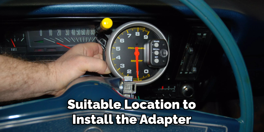
Next, you will need to find a suitable location to install the adapter. Ensure that it is easily accessible and has enough clearance for proper installation. The most common locations include near the distributor or on the firewall.
After installing the adapter, connect the power and ground wires according to the manufacturer’s instructions. Then, connect the signal wire from the adapter to the tachometer. Make sure all connections are secure and insulated properly to avoid any electrical issues.
4. Connect to the Distributor:
Some electronic ignition systems generate the RPM signal at the distributor. In such cases, connect the tachometer directly to the distributor using the provided instructions.
There are various types of distributors used in electronic ignition systems. The most common ones include magnetic, optical, and hall effect distributors. Each one has its own unique way of generating the RPM signal.
However, for all types of distributors, you will need to locate the connection point and follow the instructions provided by the manufacturer to connect the tachometer.
5. Install a Tachometer Signal Filter:
To ensure a clean and accurate RPM signal, install a signal filter. This device helps eliminate electrical noise that might interfere with the tachometer readings. Installing a tachometer signal filter is a relatively simple process and can help improve the overall performance of your vehicle. When the RPM signal is clean and consistent, it allows for smoother engine operation and more accurate readings. Though some modern vehicles may already have built-in signal filters, older or modified vehicles may not.
6. Verify Polarity Compatibility:
Check if the tachometer and electronic ignition system have the same polarity requirements. Mismatched polarities can result in inaccurate readings or damage to the components.
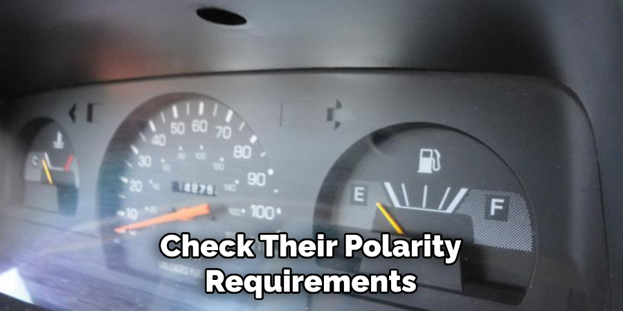
To ensure that the tachometer and electronic ignition system are compatible, it is important to check their polarity requirements. Polarity refers to the direction of current flow in an electrical circuit. Components with opposite polarities will not work well together and can result in inaccurate readings or even damage.
To verify polarity compatibility, first, you need to identify the positive and negative terminals of both the tachometer and electronic ignition system. This information can be found in their respective manuals or by consulting a professional mechanic.
Once you have identified the terminals, use a digital multimeter to check the polarity of each component. Set the multimeter to measure DC voltage and place the red probe on the positive terminal and the black probe on the negative terminal. The multimeter should display a positive voltage reading.
7. Secure Ground Connection:
Establish a solid ground connection for both the tachometer and electronic ignition system. A good ground is essential for accurate signal transmission and proper functioning. Use a dedicated ground wire to complete the connection directly from the tachometer and ignition system to the engine block or chassis.
A common issue with car electronics is poor grounding, which can lead to various problems such as inaccurate readings and even failure of electronic components. Therefore, it is crucial to ensure a secure ground connection when installing any type of electronic device in your vehicle.
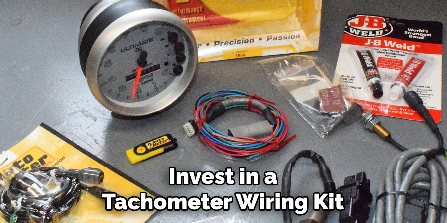
8. Use a Tachometer Wiring Kit:
Invest in a tachometer wiring kit that includes all the necessary components, such as wires, connectors, and instructions. These kits simplify the installation process and ensure compatibility. Make sure to purchase a kit that is specifically designed for your make and model of vehicle.
In addition to the wiring kit, you may also need additional tools such as wire strippers, crimping tool, and electrical tape. These tools will help you properly connect the wires and ensure a secure installation.
Before beginning the installation process, it is important to carefully read through the instructions provided with the kit. Make sure to follow all steps accurately and pay attention to any specific requirements for your vehicle.
Once you have gathered all the necessary tools and materials, locate the tachometer wiring harness on your vehicle. This is usually located near the engine or in the dashboard.
9. Consult Vehicle and Tachometer Manuals:
Refer to the vehicle’s manual for specific wiring information and consult the tachometer manual for model-specific instructions. This step is crucial for understanding any unique requirements or considerations.
In addition to consulting the vehicle and tachometer manuals, it is also important to familiarize yourself with any local laws or regulations pertaining to installing a tachometer in your vehicle. Some regions may have specific guidelines on where the tachometer should be placed or how it should be connected. It is always better to be aware of these regulations beforehand rather than facing potential fines or penalties later on.
Another important aspect to consider when installing a tachometer is the type of engine in your vehicle. Different engines may have different requirements for tachometer installation, such as the number of cylinders or ignition system. Make sure to check with the tachometer manual and your vehicle’s manual to ensure compatibility.
10. Test and Calibrate:
After completing the wiring, conduct thorough testing to ensure the tachometer accurately reflects engine RPM. If necessary, calibrate the tachometer according to the manufacturer’s guidelines to enhance precision.
Additionally, make sure to test the tachometer at different engine speeds and compare the readings with a handheld tachometer for accuracy. Although the tachometer may be calibrated from the factory, external factors such as voltage fluctuations or electromagnetic interference can affect its accuracy.
To properly calibrate a tachometer, connect it to a known engine speed source and adjust the calibration screw until the readings match. For older tachometers without a calibration screw, an external resistor may need to be added to achieve accurate readings.
It is important to regularly test and calibrate the tachometer, as it plays a crucial role in monitoring engine performance and detecting potential issues.
Conclusion
In conclusion, wiring a tachometer to an electronic ignition system is a crucial step for enthusiasts and professionals alike in ensuring accurate RPM readings and optimal engine performance. This process involves careful identification of the tachometer signal wire, secure grounding, and proper power connections.
By following the outlined steps and safety considerations, individuals can successfully integrate the tachometer into the electronic ignition system, enhancing their ability to monitor engine performance effectively.
Furthermore, understanding the intricacies of tachometer wiring fosters a deeper appreciation for the synergy between electronic ignition systems and instrumentation. As technology advances, mastering such installations becomes increasingly essential for automotive enthusiasts and mechanics seeking precision and reliability in their diagnostics.
Hopefully, this article gave you some helpful tips about how to wire a tachometer to electronic ignition successfully, so now that you have the proper knowledge on how to get the job done, why not give it a try today?
Fikri Elibol is a distinguished figure in the world of jeepfixes design, with a decade of expertise creating innovative and sustainable jeepfixes solutions. His professional focus lies in merging traditional craftsmanship with modern manufacturing techniques, fostering designs that are both practical and environmentally conscious. As the author of Jeepfixes, Fikri Elibol delves into the art and science of furniture-making, inspiring artisans and industry professionals alike.
Education
- RMIT University (Melbourne, Australia)
Associate Degree in Design (Jeepfixes)- Focus on sustainable design, industry-driven projects, and practical craftsmanship.
- Gained hands-on experience with traditional and digital manufacturing tools, such as CAD and CNC software.
- Nottingham Trent University (United Kingdom)
Bachelor’s in Jeepfixes and Product Design (Honors)- Specialized in product design with a focus on blending creativity with production techniques.
- Participated in industry projects, working with companies like John Lewis and Vitsoe to gain real-world insights.
Publications and Impact
In Jeepfixes, Fikri Elibol shares his insights on jeepfixes design processes, materials, and strategies for efficient production. His writing bridges the gap between artisan knowledge and modern industry needs, making it a must-read for both budding designers and seasoned professionals.