

Are you having problems with your car’s ignition? A ballast resistor is an essential part of ensuring that your automobile’s engine runs correctly. It helps provide the right amount of voltage to the ignition coil, preventing it from overheating and prolonging its lifespan.
Testing a ballast resistor is crucial to ensure the proper functioning of electrical circuits, especially in automotive ignition systems. The ballast resistor plays a pivotal role in regulating the voltage to the ignition coil; without it, the current might surge to a level that the coil cannot handle, potentially causing damage.
In this guide, we’ll explore the step-by-step process of how to test ballast resistor. Whether you’re a seasoned mechanic or a DIY enthusiast, following this straightforward procedure will help you diagnose issues and maintain the health of your vehicle’s electrical system.
What are the Benefits of Testing Ballast Resistors?
Testing a ballast resistor is beneficial for several reasons. First and foremost, it allows you to identify potential problems with the resistor before they become more severe. In the long run, this can save you time and money, as replacing a faulty ballast resistor is much easier and less expensive than repairing damage caused by an overheated ignition coil.
Additionally, testing a ballast resistor can also help improve the overall performance of your vehicle’s engine by ensuring that the correct amount of voltage is being supplied to the ignition system.
What Will You Need?
Before diving into the testing process, make sure you have the following items on hand:
- A multimeter
- Safety gloves and goggles
- Wire connectors (if needed)
- Electrical tape
- A clean rag or cloth
Once you have these items, you can start testing the ballast resistor.
10 Easy Steps on How to Test Ballast Resistor
Step 1: Locate the Ballast Resistor
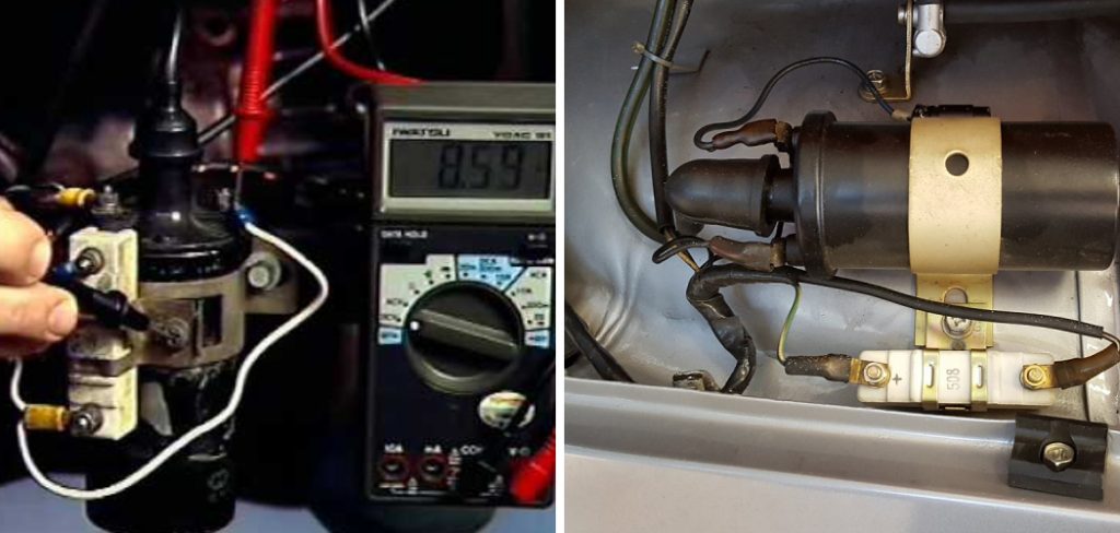
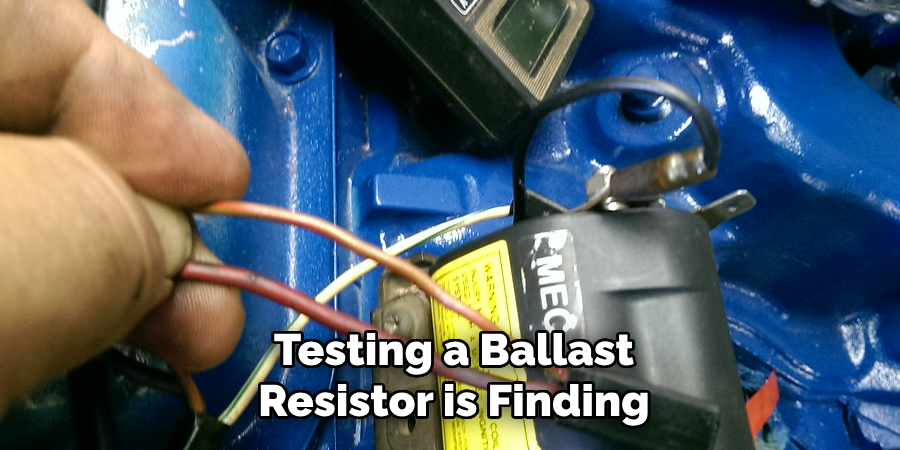
The first step in testing a ballast resistor is finding its location in your vehicle. Most often, the ballast resistor is mounted on the engine compartment’s firewall. It is typically a white ceramic block with a two-wire connection.
If you need clarification, refer to your vehicle’s service manual for the exact location. Once you have located the ballast resistor, turn off the engine and remove the keys from the ignition before proceeding to ensure your safety.
Step 2: Inspect the Ballast Resistor Visually
Before using any tools, inspecting the ballast resistor visually is wise. Check for any signs of damage, such as cracks, burns, or corrosion on the resistor itself and on the connecting wires and terminals.
If you observe any visible damage, the ballast resistor likely needs to be replaced. However, if there is no apparent damage, you should proceed with electrical testing. Make sure the ignition is off, and the key is removed before you touch any electrical parts.
Step 3: Disconnect the Wires
With the visual inspection complete and the ignition turned off, proceed to disconnect the electrical wires attached to the ballast resistor. It is essential to do this carefully; use a pair of pliers if necessary to loosen the connectors.
Remember to note how the wires are connected so you can easily reassemble them later. Once the connections are removed, you can thoroughly test the ballast resistor without interference from the rest of the vehicle’s electrical system.
Step 4: Set Your Multimeter
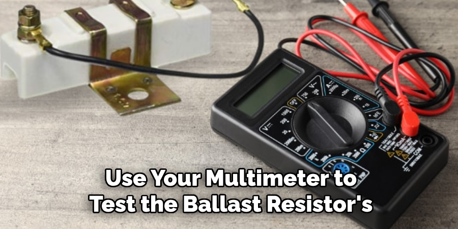
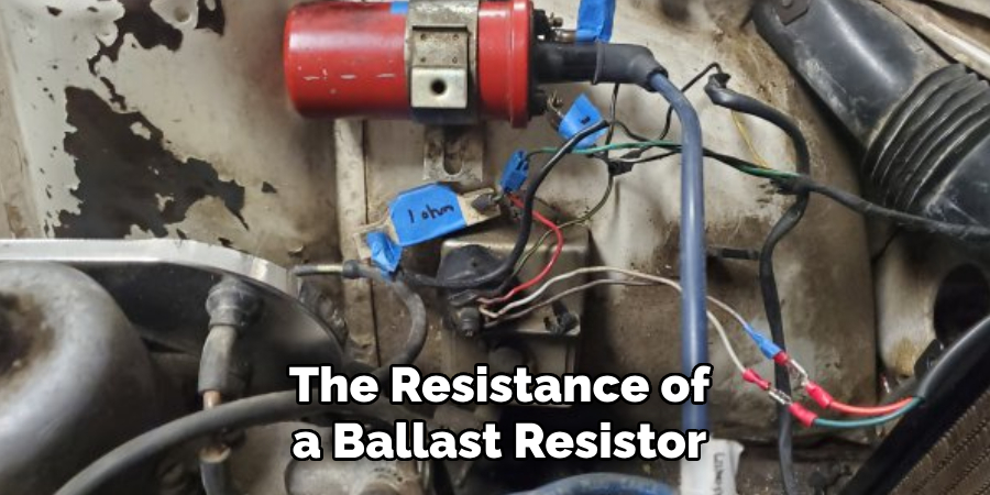
Now that you have safely disconnected the wires, it’s time to use your multimeter to test the ballast resistor’s resistance. Start by setting your multimeter to the ohms (Ω) scale. If your multimeter has multiple scales, select the one that’s appropriate for measuring resistance in the range of 1-10 ohms, as this is the typical resistance value for a ballast resistor. Ensure that the multimeter is calibrated correctly to get an accurate reading.
Step 5: Measure the Resistance
With your multimeter set to the correct ohms scale, it’s time to measure the resistance of the ballast resistor. Touch the multimeter probes to the terminals of the ballast resistor – one probe to each terminal.
It’s essential to ensure a good connection; the investigations should be in contact with the metal terminals, not just the wires. Read the measurement displayed on the multimeter. A functioning ballast resistor typically has a resistance value between 1 and 10 ohms. The ballast resistor may be faulty and require replacement if the reading is significantly outside this range.
Step 6: Check the Continuity
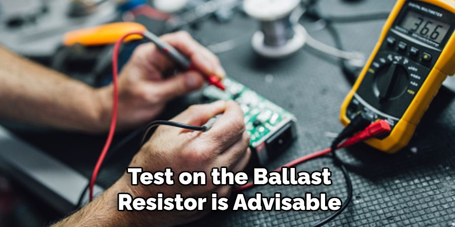
Once you have the resistance measurement, performing a continuity test on the ballast resistor is advisable. This test checks if there is an unbroken path for current to flow through the resistor. To perform this test, switch your multimeter to the continuity setting, symbolized by a sound wave or diode symbol on most multimeters.
Place the probes on the resistor’s terminals again. If the multimeter beeps or shows a continuous line (indicating zero resistance), it means that the path is clear and the resistor has continuity. If there is no beep or the display shows ‘OL’ (open loop), it indicates a break in the circuit, and the resistor is likely defective.
Step 7: Reconnect the Wires
After testing the resistance and continuity of the ballast resistor, reconnect the wires to their respective terminals. Ensure that the connections are secure and that there is no corrosion or damage on the terminals, as this could affect the performance of the ballast resistor.
If necessary, use electrical tape to reinforce the connection. Take extra care to reattach the wires as they were initially configured to avoid any potential electrical issues. Once reconnected, double-check the work to make sure everything is in order before moving on to the next step.
Step 8: Test the Ballast Resistor Under the Load
The next step is to assess the ballast resistor’s performance under load conditions. Reattach the battery if it is disconnected, and turn the ignition on, but do not start the engine. Using your multimeter, measure the voltage drop across the resistor. Connect the positive probe to one terminal and the negative probe to another.
A suitable ballast resistor should show a voltage drop; this means it is regulating the current by absorbing some of the voltage. If there is no voltage drop, the resistor may not function correctly under load and could need replacement.
Step 9: Inspect for Heat Build-Up
With the ignition still on and the engine off, monitoring the ballast resistor for any heat build-up is essential. A functioning ballast resistor will naturally get warm, as it’s designed to dissipate heat.
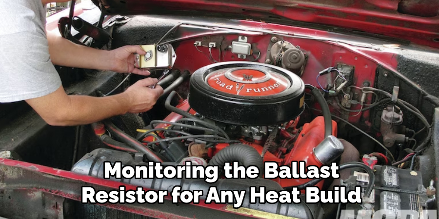
However, if it becomes too hot to touch shortly after the ignition is turned on, this may be a sign of over-resistance and could indicate a malfunction. In that case, allow the unit to cool down and then retest it to confirm the diagnosis. Be sure to handle this step cautiously—use gloves to protect yourself from potential burns.
Step 10: Final Testing and Reassembly
The final step is to perform a functional vehicle test with the ballast resistor reconnected. Start the engine and let it run for a few minutes. Observe the performance of the engine during startup and idling. Listen for smoothness in the engine’s operation and watch for any irregularities in the electrical components’ functionality. If the engine runs smoothly and all systems operate correctly, the ballast resistor is functioning as expected.
Once you are satisfied with the performance, turn off the engine and reassemble any components that had to be removed or moved aside for the ballast resistor testing. Ensure all fasteners are tightened, and all safety measures are followed during the reassembly process.
By following these steps, you can quickly test and diagnose a faulty ballast resistor. Remember to always prioritize safety by disconnecting the battery and turning off the ignition before working with any electrical components.
5 Additional Tips and Tricks
- Use a Multimeter: Set your multimeter to the ohms (Ω) setting to check the resistance of your ballast resistor. A typical reading should be within the manufacturer’s specified resistance range. Noticeable deviation could indicate a faulty resistor.
- Check for Physical Damage: Before testing, visually inspect the ballast resistor for any signs of damage, such as cracks or burn marks. Physical damage can be an early indicator of malfunction.
- Test at Various Temperatures: Remember that resistance can change with temperature. Test the resistor when it’s cold and after it has been running for a period to ensure it operates correctly at different temperatures.
- Inspect Wiring and Connections: Make sure the wires connected to the ballast resistor are in good condition and securely attached. Loose or damaged connections can lead to inaccurate test results.
- Compare Readings with a New Resistor: If you can access a new, known-to-be-good ballast resistor, compare its resistance reading with the one you are testing. If there is a significant difference, it could indicate a faulty resistor.
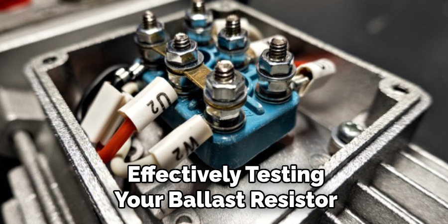
With these additional tips and tricks, you can make sure you are effectively testing your ballast resistor to ensure it is functioning correctly in your vehicle.
6 Things You Should Avoid When Testing a Ballast Resistor
- Neglecting Safety Precautions: Avoid handling the resistor or other electrical components without first ensuring the vehicle is turned off, and the keys are removed to prevent electric shock.
- Testing Without Proper Tools: Do not try to test your ballast resistor without a reliable multimeter. Using proper tools can lead to accurate results or further damage to the electrical system.
- Ignoring Manufacturer’s Specifications: Pay attention to the importance of the manufacturer’s specified resistance range. Testing outside these parameters can result in misunderstanding the health of your resistor.
- Forgetting to Isolate the Resistor: Testing the resistor while it is still fully connected to other components may yield misleading readings; ensure it is isolated to test it accurately.
- Jumping to Conclusions: Avoid hastily attributing vehicle problems to the ballast resistor without thorough testing. Other issues, such as a malfunctioning ignition coil, could be mistaken for a resistor fault.
- Assuming All Resistors are the Same: Not all ballast resistors are created equal, and using a different type or size could affect its performance. When selecting a replacement resistor, always refer to your vehicle’s specific model and make.
With these tips in mind, you can avoid common mistakes when testing your ballast resistor and ensure the accuracy of your results for proper troubleshooting and maintenance.
Some Frequently Asked Questions
1. Does a Ballast Resistor Have Polarity?
Yes, a ballast resistor does have polarity. The positive side of the resistor is typically marked with a plus sign (+), while the opposing side is marked with a minus sign (-). Installing the resistor in the correct orientation is essential for it to function correctly in your vehicle’s electrical system.
It is also important to note that some ballast resistors may not have polarity markings, so referring to the manufacturer’s instructions or a wiring diagram for proper installation is crucial. Installing the resistor with the incorrect polarity can lead to malfunctions and potential damage to the electrical system.
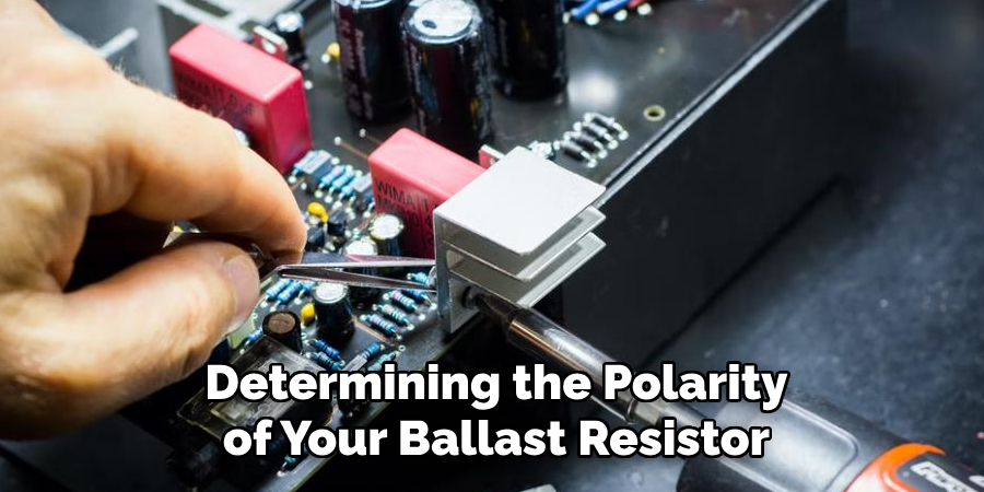
If you are still determining the polarity of your ballast resistor, it is always best to consult a professional mechanic or refer to reliable sources for guidance. Proper installation is crucial for the smooth operation of your vehicle and can prevent costly repairs in the future. Overall, understanding the polarity of a ballast resistor is essential to maintaining your vehicle’s electrical system.
2. What Happens When a Ballast Resistor Goes Bad?
When a ballast resistor goes terribly, it can cause various issues with the vehicle’s electrical system. Some common signs of a faulty ballast resistor include difficulty starting the engine, frequent stalling or misfiring, and overall poor performance.
A failed ballast resistor can also affect other components in the ignition system, such as the ignition coil or distributor. This is because the resistor’s primary function is to regulate the voltage going to these components, and proper regulation is necessary for them to function correctly.
If left unaddressed, a bad ballast resistor can also cause damage to other electrical components or lead to complete ignition failure. Therefore, it is crucial to regularly test and replace a faulty ballast resistor to ensure the smooth operation of your vehicle. Remember, prevention is always better than costly repairs, so be sure to address any issues with your ballast resistor promptly.
Overall, understanding the potential consequences of a bad ballast resistor emphasizes the importance of proper testing and maintenance.
3. What Are the Two Common Faults of Resistor?
- Open Circuit: An open circuit fault occurs when there is a break in the continuity of the resistor, resulting in no current flow and an infinite resistance reading. This can be caused by physical damage or overheating.
- Short Circuit: A short circuit fault occurs when there is an unintended connection between two points in the resistor, resulting in a high current flow and a very low resistance reading. This can be caused by damage or contamination on the resistor’s surface.
Identifying these common faults is essential for accurately testing and troubleshooting a ballast resistor to ensure it is functioning correctly in your vehicle. Regular testing and maintenance can help prevent these issues from occurring and prolong the lifespan of your resistor. So remember, when in doubt, always test your ballast resistor for accurate results and reliable performance in your vehicle.
4. How Do You Calculate Resistance?
Resistance is calculated using Ohm’s law, which states that the resistance (R) of a conductor is equal to the voltage (V) divided by the current (I). This can be represented by the formula R=V/I. The unit of measurement for resistance is ohms (Ω).
To calculate the resistance of a ballast resistor, you will need to know the voltage and current values. You can measure these values using a multimeter or refer to the manufacturer’s specifications. Once you have these values, simply plug them into the formula, and you will get the resistance value in ohms.
It is important to note that resistance can vary depending on factors such as temperature and material composition. Therefore, it is crucial to test your resistor under the same conditions and refer to the manufacturer’s specified resistance range for accurate results. Overall, understanding how to calculate resistance is essential for proper testing and troubleshooting of a ballast resistor. So, be sure to familiarize yourself with this concept when maintaining your vehicle’s electrical system.
Conclusion
Testing a ballast resistor is a straightforward but critical process in vehicle maintenance that can save time and prevent costly repairs. By following the outlined steps on how to test ballast resistor, adhering to safety precautions, and being cognizant of the common pitfalls, vehicle owners can ensure their ballast resistors are functioning correctly.
Regular testing allows for early detection of issues, ultimately contributing to a car’s longevity and reliability. Effective testing and understanding of your vehicle’s electrical system not only equip you with the knowledge to perform routine checks but also bolster your ability to make informed decisions regarding vehicle care.
Armed with a multimeter, a bit of patience, and an attentive eye for detail, you can confidently test your ballast resistor and maintain the seamless operation of your vehicle’s ignition system.

Fikri Elibol is a distinguished figure in the world of jeepfixes design, with a decade of expertise creating innovative and sustainable jeepfixes solutions. His professional focus lies in merging traditional craftsmanship with modern manufacturing techniques, fostering designs that are both practical and environmentally conscious. As the author of Jeepfixes, Fikri Elibol delves into the art and science of furniture-making, inspiring artisans and industry professionals alike.
Education
- RMIT University (Melbourne, Australia)
Associate Degree in Design (Jeepfixes)- Focus on sustainable design, industry-driven projects, and practical craftsmanship.
- Gained hands-on experience with traditional and digital manufacturing tools, such as CAD and CNC software.
- Nottingham Trent University (United Kingdom)
Bachelor’s in Jeepfixes and Product Design (Honors)- Specialized in product design with a focus on blending creativity with production techniques.
- Participated in industry projects, working with companies like John Lewis and Vitsoe to gain real-world insights.
Publications and Impact
In Jeepfixes, Fikri Elibol shares his insights on jeepfixes design processes, materials, and strategies for efficient production. His writing bridges the gap between artisan knowledge and modern industry needs, making it a must-read for both budding designers and seasoned professionals.